The following structural measures are recommended for avoiding or at least limiting the occurrence
of cracks in the dome (cf. fig. 5.23):
- For reasons of static stability, the centerpoint of the dome radius should be lowered by 0.25
R (corresponding to bottom center of the foundation). This changes the geometry of the
digester, turning it into a spherical segment, i.e. flatter and wider, which can be of
advantage for the plant as a whole.
- The foot of the dome should be made more stable and secure by letting the foundation slab
project out enough to accept an outer ring of mortar.
- A rated break/pivot ring should be provided at a point located between 1/2 and 2/3 of the
minimum slurry level. This in order to limit the occurrence or propagation of cracks in the
vicinity of the dome foot and to displace forces through its stiffening/ articulating effect such
that tensile forces are reduced around the gas space.
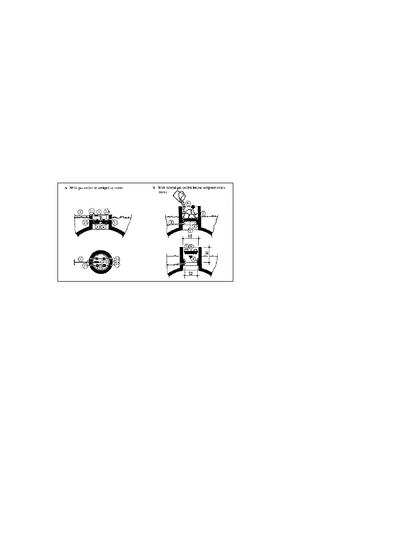
Fig. 5.24: Entry hatch of a fixed-dome
biogas plant. 1 Concrete cover, 2 Gas
pipe, 21 Flexible connection (hose), 3
Cover wedging, 31 Length of pipe
anchored in the masonry, 32 Retaining
rod, 33 Wooden/metal wedges, 4 Edge
seal made of loam/mastic compound,
5 Handles, 6 Weights, 7 Water
(Source: OEKOTOP)
In principle, however, masonry, mortar and concrete are not gaslight, with or without mortar
additives. Gastightness can only be achieved through good, careful workmanship and special-
purpose coatings. The main precondition is that the masonry and rendering be strong and free of
cracks. Cracked and sandy rendering must be removed. In most cases, a plant with cracked
masonry must be torn down, because not even the best seal coating can render cracks
permanently gaslight.
Some tried and proven seal coats:
- multilayer bitumen, applied cold (hot application poses the-danger of injury by burns and
smoke nuisance); solvents cause dangerous/explosive vapors. Two to four thick coats
required.
- bitumen with aluminum foil: thin sheets of overlapping aluminum foil applied to the still-
sticky bitumen, followed by the next coat of bitumen.
- plastics, as a rule epoxy resin or acrylic paint; very good but expensive.
- paraffin, diluted with 2 - 5% kerosene heated to 100 °C and applied to the preheated
masonry. The paraffin penetrates deep into the masonry, thus providing an effective (deep)
seal. Use kerosene/gas torch to heat masonry.
In any case, a pressure test must be performed before the plant is put in service (cf. chapter 7.1).
60