Special attention must be given to the mortar composition and proper application for rendering,
since the rendering is of decisive importance with regard to the biogas plant's durability and
leaktightness. Ensure that:
- trowelling is done vigorously (to ensure compact rendering)
- all edges and corners are rounded off
- each rendering course measures between 1.0 and 1.5 cm
- the rendering is allowed to set|dry slowly (keep shaded and moist, as necessary)
- the material composition is suitable and mutually compatible
- a rated break ring is provided for a fixed-dome plant
Crack-free rendering requires lots of pertinent experience and compliance with the above points.
Neither the rendering nor the masonry is gaslight and therefore has to be provided with a seal coat
around the gas space (cf. chapter 5.4.4).
5.4.4 Gasholder
Basically, there are three different designs/ types of construction for gasholders used in simple
biogas plants:
- integrated floating drums
- fixed domes with displacement system and
- separate gasholders
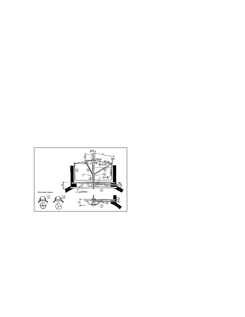
Fig. 5.22: Construction of a metal gasholder
with internal guide frame. 1 Lattice beam
serving as cross pole, 2 Cross pole with
bracing, 3 Gas pipe (2% gradient), 4 Guide
frame, 5 Braces for shape retention and
breaking up the scum layer, 6 Sheet steel (2-
4 mm) serving as the drum shell (Source:
OEKOTOP/Sasse, 1984)
Floating-drum gasholders
Most floating-drum gasholders are made of 2 - 4 mm-thick sheet steel, with the sides made
somewhat thicker than the top in order to counter the higher degree of corrosive attack. Structural
stability is provided by L-bar bracing that simultaneously serves to break up surface scum when the
drum is rotated.
A guide frame stabilizes the gas drum and keeps it from tilting and rubbing on the masonry. The two
equally suitable types used must frequently are:
- an internal rod & pipe guide with a fixed (concrete-embedded) cross pole (an advantageous
configuration in connection with an internal gas outlet)
- external guide frame supported on three wooden or steel legs (cf. fig. 5.7).
58