Steam engine
About this schools Wikipedia selection
This selection is made for schools by a children's charity read more. A quick link for child sponsorship is http://www.sponsor-a-child.org.uk/
A steam engine is a heat engine that performs mechanical work using steam as its working fluid.
Using boiling water to produce mechanical motion goes back about 2,000 years, but early devices were not practical. Since the late 1700s steam engines have become a major source of mechanical power. The first applications were removing water from mines. In 1781 James Watt patented a steam engine that produced continuous rotative motion. These 10hp engines enabled a wide range of manufacturing machinery to be powered. The engines could be sited anywhere that water and coal or wood fuel could be obtained. Within a century,in 1883, engines that could provide 10,000 hp were feasible. Steam engines could also be applied to vehicles such as traction engines and the railway locomotives which are commonly just called steam engines outside America. The stationary steam engine was an important component of the Industrial Revolution, overcoming the limitations imposed by shortage of sites suitable for water mill and allowing factories to locate where water power was unavailable.
Today steam turbines generate about 90% of the electric power in the United States using a variety of heat sources.
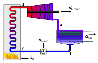
Steam engines are external combustion engines, where the working fluid is separate from the combustion products. Non-combustion heat sources such as solar power, nuclear power or geothermal energy may be used. The ideal thermodynamic cycle used to analyze this process is called the Rankine cycle. In the cycle water is heated into steam in a boiler until it reaches a high pressure. When expanded through pistons or turbines, mechanical work is done. The reduced-pressure steam is then condensed and pumped back into the boiler.
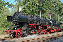
In general usage, the term steam engine can refer to either the integrated steam plants (including boilers etc.) such as railway steam locomotives and portable engines, or may refer to the piston or turbine machinery alone, as in the beam engine and stationary steam engine. Specialized devices such as steam hammers and steam pile drivers are dependent on steam supplied from a separate boiler.
History
Since the early 18th century, steam power has been applied to a variety of practical uses. At first it was applied to reciprocating pumps, but from the 1780s rotative engines (i.e. those converting reciprocating motion into rotary motion) began to appear, driving factory machinery such as spinning mules and power looms. At the turn of the 19th century, steam-powered transport on both sea and land began to make its appearance becoming ever more dominant as the century progressed.
Steam engines can be said to have been the moving force behind the Industrial Revolution and saw widespread commercial use driving machinery in factories, mills and mines; powering pumping stations; and propelling transport appliances such as railway locomotives, ships and road vehicles. Their use in agriculture led to an increase in the land available for cultivation.
The weight of boilers and condensors generally makes the power-to-weight ratio of a steam plant lower than for internal combustion engines. For mobile applications steam has been largely superseded by internal combustion engines or electric motors. However most electric power is generated using steam turbine plant, so that indirectly the world's industry is still dependent on steam power. Recent concerns about fuel sources and pollution have incited a renewed interest in steam both as a component of cogeneration processes and as a prime mover. This is becoming known as the Advanced Steam movement.
Early experiments
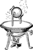
The history of the steam engine stretches back as far as the first century AD; the first recorded rudimentary steam engine being the aeolipile described by Greek mathematician Hero of Alexandria. In the following centuries, the few steam-powered "engines" known were, like the aeolipile, essentially experimental devices used by inventors to demonstrate the properties of steam. A rudimentary steam turbine device was described by Taqi al-Din in 1551 and by Giovanni Branca in 1629. Jerónimo de Ayanz y Beaumont received patents in 1606 for fifty steam powered inventions, including a water pump for draining inundated mines. Denis Papin, a Huguenot refugee, did some useful work on the steam digester in 1679, and first used a piston to raise weights in 1690.
Pumping engines
The first commercial steam-powered device was a water pump, developed in 1698 by Thomas Savery. It used a vacuum to raise water from below, then used steam pressure to raise it higher. Small engines were effective though larger models were problematic. They proved only to have a limited lift height and were prone to boiler explosions. It received some use in mines, pumping stations and for supplying water wheels used to power textile machinery. An attractive feature of the Savery engine was its low cost. It continued to be manufactured until the late 18th century. One engine was still known to be operating in 1820.
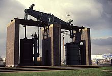
The first commercially successful true engine was the atmospheric engine, invented by Thomas Newcomen around 1712. It made use of technologies discovered by Savery and Papin. Newcomen's engine was relatively inefficient, and in most cases was used for pumping water. It worked by creating a partial vacuum by condensing steam under a piston within a cylinder. It was employed for draining mine workings at depths hitherto impossible, and also for providing a reusable water supply for driving waterwheels at factories sited away from a suitable "head". Water that had passed over the wheel was pumped back up into a storage reservoir above the wheel.
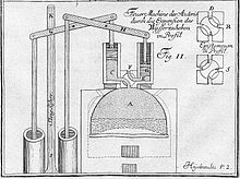
In 1720 Jacob Leupold described a two-cylinder high pressure steam engine. The invention was published in his major work "Theatri Machinarum Hydraulicarum". The engine used two lead-weighted pistons providing a continuous motion to a water pump. Each piston was raised by the steam pressure and returned to its original position by gravity. The two pistons shared a common four way rotary valve connected directly to a steam boiler.
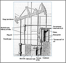
The next major step occurred when James Watt developed (1763–75) an improved version of Newcomen's engine, with a separate condenser. Boulton and Watt's early engines used half as much coal as John Smeaton's improved version of Newcomen's. Newcomen's and Watt's early engines were "atmospheric". They were powered by air pressure pushing a piston into the partial vacuum generated by condensing steam, instead of the pressure of expanding steam. The engine cylinders had to be large because the only usable force acting on them was due to atmospheric pressure.
Watt proceeded to develop his engine further, modifying it to provide a rotary motion suitable for driving factory machinery. This enabled factories to be sited away from rivers, and further accelerated the pace of the Industrial Revolution.
Around 1800 Richard Trevithick and, separately, Oliver Evans in 1801 introduced engines using high-pressure steam; Trevithick obtained his high-pressure engine patent in 1802. These were much more powerful for a given cylinder size than previous engines and could be made small enough for transport applications. Thereafter, technological developments and improvements in manufacturing techniques (partly brought about by the adoption of the steam engine as a power source) resulted in the design of more efficient engines that could be smaller, faster, or more powerful, depending on the intended application.
The Cornish engine was developed by Trevithick and others in the 1810s. It was a compound cycle engine that used high pressure steam expansively, then condensed the low pressure steam, making it relatively efficient. The Cornish engine had irregular motion and torque though the cycle, limiting it mainly to pumping. Cornish engines were used in mines and for water supply until the late 19th century.
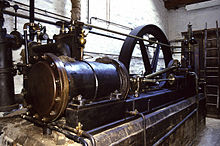
Horizontal stationary engine
The Corliss steam engine, a four-valve counter flow engine with separate steam admission and exhaust valves and automatic variable steam cut off, was called the most significant advance in the steam engine since James Watt. In addition to using 30% less steam it provided more uniform speed, making it well suited to manufacturing, especially cotton spinning.
Marine engines
Near the end of the 19th century compound engines came into widespread use. Compound engines exhausted steam in to successively larger cylinders to accommodate the higher volumes at reduced pressures, giving improved efficiency. These stages were called expansions, with double and triple expansion engines being common, especially in shipping where efficiency was important to reduce the weight of coal carried.
Steam engines remained the dominant source of power until the early 20th century, when advances in the design of electric motors and internal combustion engines gradually resulted in the replacement of reciprocating (piston) steam engines in commercial usage, and the ascendancy of steam turbines in power generation. Today most steam power is provided by turbines.
Steam locomotives
As the development of steam engines progressed through the 18th century, various attempts were made to apply them to road and railway use. In 1784, William Murdoch, a Scottish inventor, built a prototype steam road locomotive. An early working model of a steam rail locomotive was designed and constructed by steamboat pioneer John Fitch in the United States probably during the 1780s or 1790s. His steam locomotive used interior bladed wheels guided by rails or tracks.
The first full-scale working railway steam locomotive was built by Richard Trevithick in the United Kingdom and, on 21 February 1804, the world's first railway journey took place as Trevithick's unnamed steam locomotive hauled a train along the tramway from the Pen-y-darren ironworks, near Merthyr Tydfil to Abercynon in south Wales. The design incorporated a number of important innovations that included using high-pressure steam which reduced the weight of the engine and increased its efficiency. Trevithick visited the Newcastle area later in 1804 and the colliery railways in north-east England became the leading centre for experimentation and development of steam locomotives. Trevithick continued his own experiments using a trio of locomotives, concluding with the Catch Me Who Can in 1808. Only four years later, the successful twin-cylinder locomotive Salamanca by Matthew Murray was used by the edge railed rack and pinion Middleton Railway. In 1825 George Stephenson built the Locomotion for the Stockton and Darlington Railway. This was the first public steam railway in the world and then in 1829, he built The Rocket which was entered in and won the Rainhill Trials. The Liverpool and Manchester Railway opened in 1830 making exclusive use of steam power for both passenger and freight trains.
Steam locomotives continued to be manufactured until the late twentieth century in places such as China and the former East Germany.
Steam turbines
The final major evolution of the steam engine design was the use of steam turbines starting in the late part of the 19th century. Turbines are more efficient than pistons, have fewer moving parts, and provide rotary power directly instead of through a connecting rod system or similar means. Steam turbines entirely replaced reciprocating engines in electricity generating stations after the turn of the 20th century, where their efficiency, higher speed and smooth rotation were advantages and their inflexibility in optimum speed was unimportant. Turbines were extensively applied for propulsion of large ships for similar reasons.
Present development
Although the reciprocating steam engine is no longer in widespread commercial use, various companies are exploring or exploiting the potential of the engine as an alternative to internal combustion engines.The company Energiprojekt AB in Sweden has made progress in using modern materials for harnessing the power of steam. The efficiency of Energiprojekt's steam engine reaches some 27-30% on high-pressure engines. It is a single-step, 5-cylinder engine (no compound) with superheated steam and consumes approx. 4 kg (8.8 lb) of steam per kWh.
Components and accessories of steam engines
There are two fundamental components of a steam plant: the boiler or steam generator, and the "motor unit", referred to itself as a "steam engine". Stationary steam engines in fixed buildings may have the boiler and engine in separate buildings some distance apart. For portable or mobile use, such as steam locomotives, the two are mounted together.
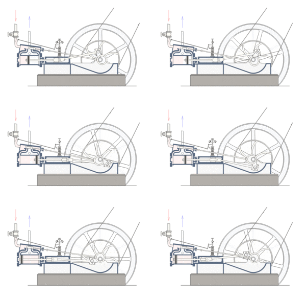
The widely used reciprocating engine typically consisted of a cast iron cylinder, piston, connecting rod and beam or a crank and flywheel, and miscellaneous linkages. Steam was alternately supplied and exhausted by one or more valves. Speed control was either automatic, using a governor, or by a manual valve. The cylinder casting contained steam supply and exhaust ports.
Engines equipped with a condenser are a separate type than those that exhaust to the atmosphere.
Other components are often present; pumps (such as an injector) to supply water to the boiler during operation, condensers to recirculate the water and recover the latent heat of vaporisation, and superheaters to raise the temperature of the steam above its saturated vapour point, and various mechanisms to increase the draft for fireboxes. When coal is used, a chain or screw stoking mechanism and its drive engine or motor may be included to move the fuel from a supply bin (bunker) to the firebox. See: Mechanical stoker
Boilers
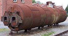
Boilers are pressure vessels that contain water to be boiled, and some kind of mechanism for transferring the heat to the water so as to boil it.
The two most common methods of transferring heat to the water are:
- water-tube boiler - water is contained in or run through one or several tubes surrounded by hot gases
- fire-tube boiler - the water partially fills a vessel below or inside which is a combustion chamber or furnace and fire tubes through which the hot gases flow
Fire tube boilers were the main type used for early high pressure steam, but they were displaced by safer water tube boilers in the late 19th century.
Once turned to steam, many boilers raise the temperature of the steam further, turning ' wet steam' into ' superheated steam'. This use of superheating avoids the steam condensing within the engine, and allows significantly greater efficiency.
Motor units
A motor unit takes a supply of steam at high pressure and temperature and gives out a supply of steam at lower pressure and temperature, using as much of the difference in steam energy as possible to do mechanical work. Motor units are typically a type of piston or steam turbine.
A motor unit is often called 'steam engine' in its own right. They will also operate on compressed air or other gas.
Cold sink
As with all heat engines, a considerable quantity of waste heat at relatively low temperature is produced and must be disposed of.
The simplest cold sink is to vent the steam to the environment. This is often used on steam locomotives, as the released steam is released in the chimney so as to increase the draw on the fire, which greatly increases engine power, but is inefficient. Condensing steam locomotives have been built, but only for special applications such as working in tunnels and where supplies of water are scarce.
Sometimes the waste heat is useful in and of itself, and in those cases very high overall efficiency can be obtained. For example, combined heat and power (CHP) systems use the waste steam for district heating.
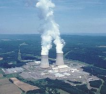
Where CHP is not used, steam turbines in power stations use surface condensers as a cold sink. The condensers are cooled by water flow from oceans, rivers, lakes, and often by cooling towers which evaporate water to provide cooling energy removal. The resulting condensed hot water output from the condenser is then put back into the boiler via a pump. A dry type cooling tower is similar to an automobile radiator and is used in locations where water is costly. Evaporative (wet) cooling towers use the rejected heat to evaporate water; this water is kept separate from the condensate, which circulates in a closed system and returns to the boiler. Such towers often have visible plumes due to the evaporated water condensing into droplets carried up by the warm air. Evaporative cooling towers need less water flow than "once-through" cooling by river or lake water; a 700 megawatt coal-fired power plant may use about 3600 cubic metres of make-up water every hour for evaporative cooling, but would need about twenty times as much if cooled by river water.
Water pump
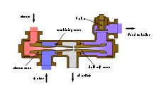
The Rankine cycle and most practical steam engines have a water pump to recycle or top up the boiler water, so that they may be run continuously. Utility and industrial boilers commonly use multi-stage centrifugal pumps; however, other types are used. Another means of supplying lower pressure boiler feed water is an injector, which uses a steam jet usually supplied from the boiler. Injectors became popular in the 1850s but are no longer widely used, except in applications such as steam locomotives.
Monitoring and control
For safety reasons, nearly all steam engines are equipped with mechanisms to monitor the boiler, such as a pressure gauge and a sight glass to monitor the water level.
Many engines, stationary and mobile, are also fitted with a governor to regulate the speed of the engine without the need for human interference (similar to cruise control in some cars).
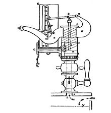
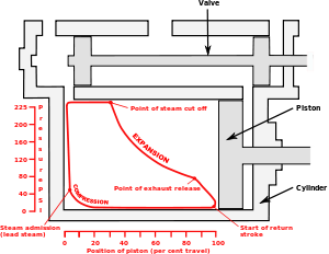
The most useful instrument for analyzing the performance of steam engines is the steam engine indicator. Early versions were in use by 1851, but the most successful indicator was developed for the high speed engine inventor and manufacturer Charles Porter by Charles Richard and exhibited at London Exhibition in 1862. The steam engine indicator traces on paper the pressure in the cylinder throughout the cycle, which can be used to spot various problems and calculate developed horsepower. It was routinely used by engineers, mechanics and insurance inspectors. The engine indicator can also be used on internal combustion engines. See image of indicator diagram below.
Engine configuration
Simple engine
In a simple engine the charge of steam works only once in a cylinder. It is then exhausted directly into the atmosphere or into a condenser.
Compound engines
As steam expands in a high pressure engine its temperature drops because no heat is added to the system; this is known as adiabatic expansion and results in steam entering the cylinder at high temperature and leaving at low temperature. This causes a cycle of heating and cooling of the cylinder with every stroke which is a source of inefficiency. A method to lessen the magnitude of this heating and cooling was invented in 1804 by British engineer Arthur Woolf, who patented his Woolf high pressure compound engine in 1805. In the compound engine, high pressure steam from the boiler expands in a high pressure (HP) cylinder and then enters one or more subsequent lower pressure (LP) cylinders. The complete expansion of the steam now occurs across multiple cylinders and as less expansion now occurs in each cylinder less heat is lost by the steam in each. This reduces the magnitude of cylinder heating and cooling, increasing the efficiency of the engine. By staging the expansion in multiple cylinders, torque variability can be reduced. To derive equal work from lower pressure steam requires a larger cylinder volume as this steam occupies a greater volume. Therefore the bore, and often the stroke, are increased in low pressure cylinders resulting in larger cylinders.
Double expansion (usually known as compound) engines expanded the steam in two stages. The pairs may be duplicated or the work of the large low pressure cylinder can be split with one high pressure cylinder exhausting into one or the other, giving a 3-cylinder layout where cylinder and piston diameter are about the same making the reciprocating masses easier to balance.
Two-cylinder compounds can be arranged as:
- Cross compounds - The cylinders are side by side.
- Tandem compounds - The cylinders are end to end, driving a common connecting rod
- Angle compounds - The cylinders are arranged in a vee (usually at a 90° angle) and drive a common crank.
With two-cylinder compounds used in railway work, the pistons are connected to the cranks as with a two-cylinder simple at 90° out of phase with each other (quartered). When the double expansion group is duplicated, producing a 4-cylinder compound, the individual pistons within the group are usually balanced at 180°, the groups being set at 90° to each other. In one case (the first type of Vauclain compound), the pistons worked in the same phase driving a common crosshead and crank, again set at 90° as for a two-cylinder engine. With the 3-cylinder compound arrangement, the LP cranks were either set at 90° with the HP one at 135° to the other two, or in some cases all three cranks were set at 120°.
The adoption of compounding was common for industrial units, for road engines and almost universal for marine engines after 1880; it was not universally popular in railway locomotives where it was often perceived as complicated. This is partly due to the harsh railway operating environment and limited space afforded by the loading gauge (particularly in Britain, where compounding was never common and not employed after 1930). However, although never in the majority, it was popular in many other countries.
Multiple expansion engines
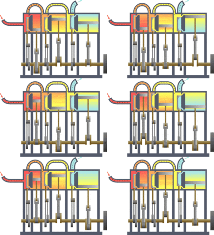
It is a logical extension of the compound engine (described above) to split the expansion into yet more stages to increase efficiency. The result is the multiple expansion engine. Such engines use either three or four expansion stages and are known as triple and quadruple expansion engines respectively. These engines use a series of cylinders of progressively increasing diameter. These cylinders are designed to divide the work into equal shares for each expansion stage. As with the double expansion engine, if space is at a premium, then two smaller cylinders may be used for the low pressure stage. Multiple expansion engines typically had the cylinders arranged inline, but various other formations were used. In the late 19th century, the Yarrow-Schlick-Tweedy balancing 'system' was used on some marine triple expansion engines. Y-S-T engines divided the low pressure expansion stages between two cylinders, one at each end of the engine. This allowed the crankshaft to be better balanced, resulting in a smoother, faster-responding engine which ran with less vibration. This made the 4-cylinder triple-expansion engine popular with large passenger liners (such as the Olympic class), but this was ultimately replaced by the virtually vibration-free turbine (see below).
The image to the right shows an animation of a triple expansion engine. The steam travels through the engine from left to right. The valve chest for each of the cylinders is to the left of the corresponding cylinder.
Land-based steam engines could exhaust much of their steam, as feed water was usually readily available. Prior to and during World War I, the expansion engine dominated marine applications where high vessel speed was not essential. It was however superseded by the British invention steam turbine where speed was required, for instance in warships, such as the dreadnought battleships, and ocean liners. HMS Dreadnought of 1905 was the first major warship to replace the proven technology of the reciprocating engine with the then-novel steam turbine.
Types of motor units
Reciprocating piston
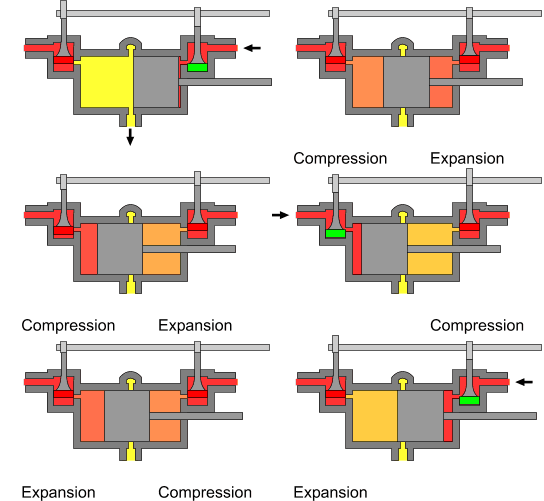
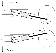
In most reciprocating piston engines, the steam reverses its direction of flow at each stroke (counterflow), entering and exhausting from the cylinder by the same port. The complete engine cycle occupies one rotation of the crank and two piston strokes; the cycle also comprises four events – admission, expansion, exhaust, compression. These events are controlled by valves often working inside a steam chest adjacent to the cylinder; the valves distribute the steam by opening and closing steam ports communicating with the cylinder end(s) and are driven by valve gear, of which there are many types. The simplest valve gears give events of fixed length during the engine cycle and often make the engine rotate in only one direction. Most however have a reversing mechanism which additionally can provide means for saving steam as speed and momentum are gained by gradually "shortening the cutoff" or rather, shortening the admission event; this in turn proportionately lengthens the expansion period. However, as one and the same valve usually controls both steam flows, a short cutoff at admission adversely affects the exhaust and compression periods which should ideally always be kept fairly constant; if the exhaust event is too brief, the totality of the exhaust steam cannot evacuate the cylinder, choking it and giving excessive compression ("kick back").
In the 1840s and 50s, there were attempts to overcome this problem by means of various patent valve gears with a separate, variable cutoff expansion valve riding on the back of the main slide valve; the latter usually had fixed or limited cutoff. The combined setup gave a fair approximation of the ideal events, at the expense of increased friction and wear, and the mechanism tended to be complicated. The usual compromise solution has been to provide lap by lengthening rubbing surfaces of the valve in such a way as to overlap the port on the admission side, with the effect that the exhaust side remains open for a longer period after cut-off on the admission side has occurred. This expedient has since been generally considered satisfactory for most purposes and makes possible the use of the simpler Stephenson, Joy and Walschaerts motions. Corliss, and later, poppet valve gears had separate admission and exhaust valves driven by trip mechanisms or cams profiled so as to give ideal events; most of these gears never succeeded outside of the stationary marketplace due to various other issues including leakage and more delicate mechanisms.
- Compression
Before the exhaust phase is quite complete, the exhaust side of the valve closes, shutting a portion of the exhaust steam inside the cylinder. This determines the compression phase where a cushion of steam is formed against which the piston does work whilst its velocity is rapidly decreasing; it moreover obviates the pressure and temperature shock, which would otherwise be caused by the sudden admission of the high pressure steam at the beginning of the following cycle.
- Lead
The above effects are further enhanced by providing lead: as was later discovered with the internal combustion engine, it has been found advantageous since the late 1830s to advance the admission phase, giving the valve lead so that admission occurs a little before the end of the exhaust stroke in order to fill the clearance volume comprising the ports and the cylinder ends (not part of the piston-swept volume) before the steam begins to exert effort on the piston.
Uniflow (or unaflow) engine
Uniflow engines attempt to remedy the difficulties arising from the usual counterflow cycle where, during each stroke, the port and the cylinder walls will be cooled by the passing exhaust steam, whilst the hotter incoming admission steam will waste some of its energy in restoring working temperature. The aim of the uniflow is to remedy this defect and improve efficiency by providing an additional port uncovered by the piston at the end of each stroke making the steam flow only in one direction. By this means, the simple-expansion uniflow engine gives efficiency equivalent to that of classic compound systems with the added advantage of superior part-load performance, and comparable efficiency to turbines for smaller engines below one thousand horsepower. However, the thermal expansion gradient uniflow engines produce along the cylinder wall gives practical difficulties.
Turbine engines
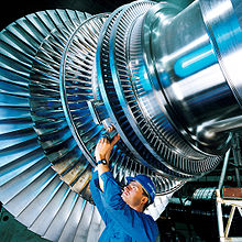
A steam turbine consists of one or more rotors (rotating discs) mounted on a drive shaft, alternating with a series of stators (static discs) fixed to the turbine casing. The rotors have a propeller-like arrangement of blades at the outer edge. Steam acts upon these blades, producing rotary motion. The stator consists of a similar, but fixed, series of blades that serve to redirect the steam flow onto the next rotor stage. A steam turbine often exhausts into a surface condenser that provides a vacuum. The stages of a steam turbine are typically arranged to extract the maximum potential work from a specific velocity and pressure of steam, giving rise to a series of variably sized high and low pressure stages. Turbines are only effective if they rotate at very high speed, therefore they are usually connected to reduction gearing to drive another mechanism, such as a ship's propeller, at a lower speed. This gearbox can be mechanical but today it is more common to use an alternator/generator set to produce electricity that later is used to drive an electric motor. A turbine rotor is also only capable of providing power when rotating in one direction. Therefore a reversing stage or gearbox is usually required where power is required in the opposite direction.
Steam turbines provide direct rotational force and therefore do not require a linkage mechanism to convert reciprocating to rotary motion. Thus, they produce smoother rotational forces on the output shaft. This contributes to a lower maintenance requirement and less wear on the machinery they power than a comparable reciprocating engine.
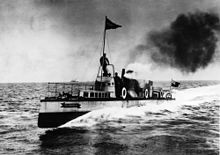
The main use for steam turbines is in electricity generation (about 90% of the world's electric production is by use of steam turbines) and to a lesser extent as marine prime movers. In the former, the high speed of rotation is an advantage, and in both cases the relative bulk is not a disadvantage; in the latter (pioneered on the Turbinia), the light weight, high efficiency and high power are highly desirable.
Virtually all nuclear power plants generate electricity by heating water to provide steam that drives a turbine connected to an electrical generator. Nuclear-powered ships and submarines either use a steam turbine directly for main propulsion, with generators providing auxiliary power, or else employ turbo-electric propulsion, where the steam drives a turbine-generator set with propulsion provided by electric motors. A limited number of steam turbine railroad locomotives were manufactured. Some non-condensing direct-drive locomotives did meet with some success for long haul freight operations in Sweden and for express passenger work in Britain, but were not repeated. Elsewhere, notably in the U.S.A., more advanced designs with electric transmission were built experimentally, but not reproduced. It was found that steam turbines were not ideally suited to the railroad environment and these locomotives failed to oust the classic reciprocating steam unit in the way that modern diesel and electric traction has done.
Oscillating cylinder steam engines
An oscillating cylinder steam engine is a variant of the simple expansion steam engine which does not require valves to direct steam into and out of the cylinder. Instead of valves, the entire cylinder rocks, or oscillates, such that one or more holes in the cylinder line up with holes in a fixed port face or in the pivot mounting ( trunnion). These engines are mainly used in toys and models, because of their simplicity, but have also been used in full size working engines, mainly on ships where their compactness is valued.
Rotary steam engines
It is possible to use a mechanism based on a pistonless rotary engine such as the Wankel engine in place of the cylinders and valve gear of a conventional reciprocating steam engine. Many such engines have been designed, from the time of James Watt to the present day, but relatively few were actually built and even fewer went into quantity production; see link at bottom of article for more details. The major problem is the difficulty of sealing the rotors to make them steam-tight in the face of wear and thermal expansion; the resulting leakage made them very inefficient. Lack of expansive working, or any means of control of the cutoff is also a serious problem with many such designs. By the 1840s, it was clear that the concept had inherent problems and rotary engines were treated with some derision in the technical press. However, the arrival of electricity on the scene, and the obvious advantages of driving a dynamo directly from a high-speed engine, led to something of a revival in interest in the 1880s and 1890s, and a few designs had some limited success.
Of the few designs that were manufactured in quantity, those of the Hult Brothers Rotary Steam Engine Company of Stockholm, Sweden, and the spherical engine of Beauchamp Tower are notable. Tower's engines were used by the Great Eastern Railway to drive lighting dynamos on their locomotives, and by the Admiralty for driving dynamos on board the ships of the Royal Navy. They were eventually replaced in these niche applications by steam turbines.
Rocket type
The aeolipile represents the use of steam by the rocket-reaction principle, although not for direct propulsion.
In more modern times there has been limited use of steam for rocketry – particularly for rocket cars. The technique is simple in concept, simply fill a pressure vessel with hot water at high pressure, and open a valve leading to a suitable nozzle. The drop in pressure immediately boils some of the water and the steam leaves through a nozzle, giving a significant propulsive force.
Safety
Steam engines possess boilers and other components that are pressure vessels that contain a great deal of potential energy. Steam escapes and boiler explosions (typically BLEVEs) can and have caused great loss of life in the past. While variations in standards may exist in different countries, stringent legal, testing, training, care with manufacture, operation and certification is applied to ensure safety. See: Pressure vessel
Failure modes may include:
- over-pressurisation of the boiler
- insufficient water in the boiler causing overheating and vessel failure
- build up of sediment and scale which caused local hot spots, especially in riverboats using dirty feed water
- pressure vessel failure of the boiler due to inadequate construction or maintenance.
- escape of steam from pipework/boiler causing scalding
Steam engines frequently possess two independent mechanisms for ensuring that the pressure in the boiler does not go too high; one may be adjusted by the user, the second is typically designed as an ultimate fail-safe. Such safety valves traditionally used a simple lever to restrain a plug valve in the top of a boiler. One end of the lever carried a weight or spring that restrained the valve against steam pressure. Early valves could be adjusted by engine drivers, leading to many accidents when a driver fastened the valve down to allow greater steam pressure and more power from the engine. The more recent type of safety valve uses a non-adjustable spring-loaded valve. This type is normally not adjustable and is considerably safer.
Lead fusible plugs may be present in the crown of the firebox. If the water level drops, such that the temperature of the firebox crown increases significantly, the lead melts and the steam escapes, warning the operators, who may then manually drop the fire. Except in the smallest of boilers the steam escape has little effect on dampening the fire. The plugs are also too small in area to lower steam pressure significantly, depressurizing the boiler. If they were any larger, the volume of escaping steam would itself endanger the crew.
Steam cycle
The Rankine cycle is the fundamental thermodynamic underpinning of the steam engine. The cycle is a mathematical model that illustrates the flow of the working fluid (steam) in an engine with the heat added being converted to work and then the work being dissipated as waste heat. The heat is supplied externally to a closed loop. This, in steam engines contains water and steam. The cycle is used to explain machines that generate about 90% of all electric power used throughout the world, including virtually all solar, biomass, coal and nuclear power plants. It is named after William John Macquorn Rankine, a Scottish polymath.
The Rankine cycle is sometimes referred to as a practical Carnot cycle because, when an efficient turbine is used, the TS diagram begins to resemble the Carnot cycle. The main difference is that heat addition (in the boiler) and rejection (in the condenser) are isobaric (constant pressure) processes in the Rankine cycle and isothermal (constant temperature) processes in the theoretical Carnot cycle. In this cycle a pump is used to pressurize the working fluid which is received from the condenser as a liquid not as a gas. Pumping the working fluid in liquid form during the cycle requires a small fraction of the energy to transport it compared to the energy needed to compress the working fluid in gaseous form in a compressor (as in the Carnot cycle). The cycle of a reciprocating steam engine differs from that of turbines because of condensation and re-evaporation occurring in the cylinder or in the steam inlet passages.
The working fluid in a Rankine cycle follows a closed loop and is reused constantly. Normally water is the fluid of choice due to its favourable properties, such as non-toxic and unreactive chemistry, abundance, low cost, and its thermodynamic properties. Mercury is the working fluid in the mercury vapor turbine. Low boiling hydrocarbons can be used in a binary cycle.
The steam engine contributed much to the development of thermodynamic theory; however, the only applications of scientific theory that influenced the steam engine were the original concepts of harnessing the power of steam and atmospheric pressure and knowledge of properties of heat and steam. The experimental measurements made by Watt on a model steam engine led to the development of the separate condenser. Watt independently discovered latent heat, which was confirmed by Joseph Black who also advised Watt on experimental procedures. Watt was also aware of the change in the boiling point of water with pressure. Otherwise, the improvements to the engine itself were more mechanical in nature. The thermodynamic concepts of the Rankine cycle did give engineers the understanding needed to calculate efficiency which aided the development of modern high pressure and temperature boilers and the steam turbine.
Efficiency
-
- See also: Engine efficiency#Steam engine
The efficiency of an engine can be calculated by dividing the energy output of mechanical work that the engine produces by the energy input to the engine by the burning fuel.
The historical measure of a steam engine's energy efficiency was its "duty". The concept of duty was first introduced by Watt in order to illustrate how much more efficient his engines were over the earlier Newcomen designs. Duty is the number of foot-pounds of work delivered by burning one bushel (94 pounds) of coal. The best examples of Newcomen designs had a duty of about 7 million, but most were closer to 5 million. Watt's original low-pressure designs were able to deliver duty as high as 25 million, but averaged about 17. This was a three-fold improvement over the average Newcomen design. Early Watt engines equipped with high-pressure steam improved this to 65 million.
No heat engine can be more efficient than the Carnot cycle, in which heat is moved from a high temperature reservoir to one at a low temperature, and the efficiency depends on the temperature difference. For the greatest efficiency, steam engines should be operated at the highest steam temperature possible ( superheated steam), and release the waste heat at the lowest temperature possible.
The efficiency of a Rankine cycle is usually limited by the working fluid. Without the pressure reaching super critical levels for the working fluid, the temperature range the cycle can operate over is quite small; in steam turbines, turbine entry temperatures are typically 565°C (the creep limit of stainless steel) and condenser temperatures are around 30°C. This gives a theoretical Carnot efficiency of about 63% compared with an actual efficiency of 42% for a modern coal-fired power station. This low turbine entry temperature (compared with a gas turbine) is why the Rankine cycle is often used as a bottoming cycle in combined-cycle gas turbine power stations.
One of the principal advantages the Rankine cycle holds over others is that during the compression stage relatively little work is required to drive the pump, the working fluid being in its liquid phase at this point. By condensing the fluid, the work required by the pump consumes only 1% to 3% of the turbine power and contributes to a much higher efficiency for a real cycle. The benefit of this is lost somewhat due to the lower heat addition temperature. Gas turbines, for instance, have turbine entry temperatures approaching 1500°C. Nonetheless, the efficiencies of actual large steam cycles and large modern gas turbines are fairly well matched.
In practice, a steam engine exhausting the steam to atmosphere will typically have an efficiency (including the boiler) in the range of 1-10%, but with the addition of a condenser and multiple expansion, it may be greatly improved to 25% or better.
A modern large electrical power station (producing several hundred megawatts of electrical output) with steam reheat, economizer etc. will achieve efficiency in the mid 40% range, with the most efficient units approaching 50% thermal efficiency.
It is also possible to capture the waste heat using cogeneration in which the waste heat is used for heating a lower boiling point working fluid or as a heat source for district heating via saturated low pressure steam. By this means it is possible to use as much as 85-90% of the input energy.
